Using Adafruit’s Bluefruit nRF52 Feather bootloader on a cheap chinese board.

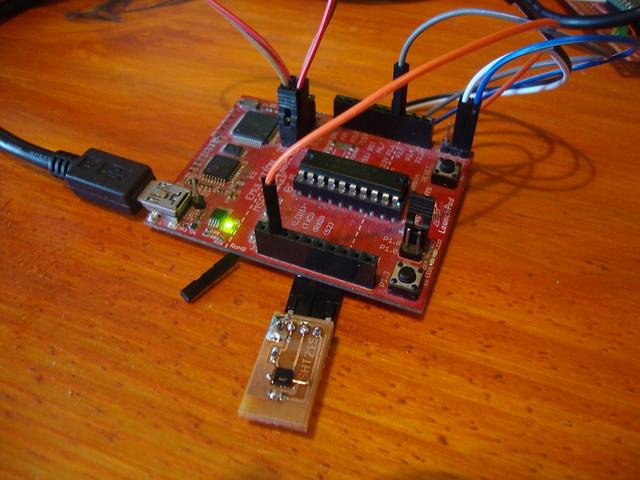
I have one of these E73-TBB Test Board for an nRF52832 module. The board is only U$S10 and Ebay was handing out U$S5 off coupons, so it ended costing me the same as the bare bluetooth module. The board comes with a USB-to-serial converter, a couple of leds and a couple of switches, nothing too fancy. I don’t have a programmer for this board but I bought it anyways thinking that it could be possible to use with the Arduino environment.

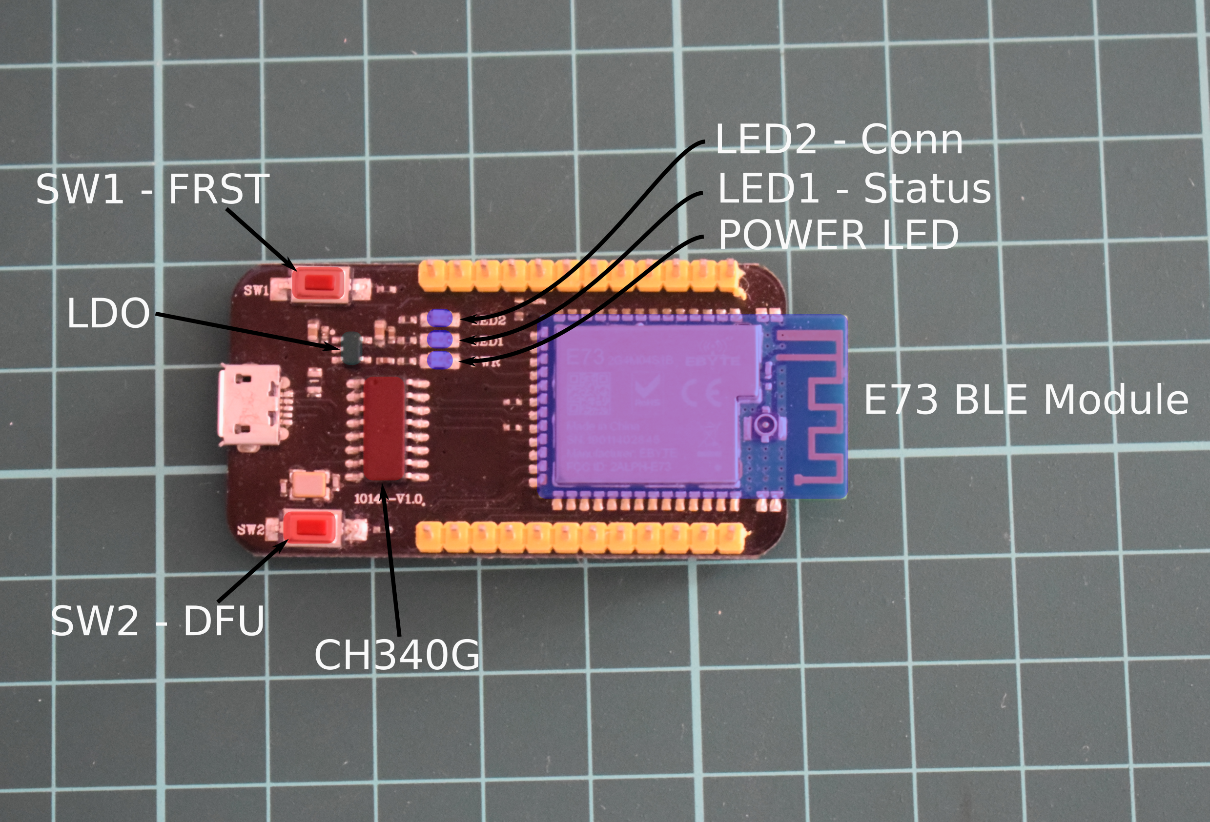
E73 TBB Board with main components highlighted

The module itself is a E73-2G4M04S1B (for which there is a manual available) but there isn’t much information about the board. As a first step I had to figure it out how everything is connected, from that I got this schematic:

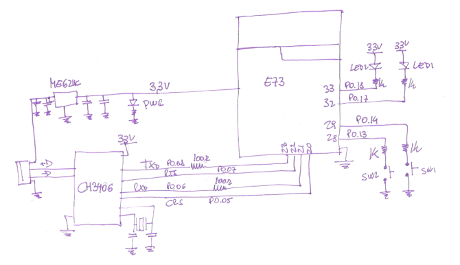
E73-TBB Test Board For nRF52832 schematic

The layout is quite similar to other boards like SparkFun’s nRF52832 Breakout or Adafruit’s Bluefruit nRF52 Feather. There is even a board whit the same module with the leds, switches and UART wired as a Bluefruit nRF52, this allows them to use Adafruit’s bootloader without any modifications. What I’m lacking is a switch on the reset line but that is not such a big isuue.

I started with Sparkfun bootloader whitout much luck, not sure what the problem was, and then with Adafruit’s bootloader. Thankfully the people at Adafruit have make it really easy to use it and modify it with a superb documentation.

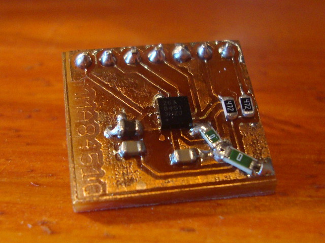
E73 board coneected to a J-Link EDU through an adapter board we made at work.

The only files I had to modify is the Makefile (just to correct path to some tools) and the board.h file for the nrf52832 feather. In this last file you’ll find the definition of the pins used for the leds, switches and UART. So, It was just a matter of changing the values to match the wiring on my board.

Original and modified

Now, I can’t say the rest of the process went smoothly. I could flash the bootloader in the board (using a J-Link from work 😉 ) but the Arduino software didn’t recognize it whenever I tried to flash something on it.

I was trying different things until I found a sequence of events that make it work. You have the possibility to update the bootloader in Adafruit’s board in Arduino using a J-Link.

I tried that and worked great , but now I had the wrong bootloader in the board. I immediately flash the modified bootloader directly with the J-link

And that somehow made the trick. Not sure why this is, if somebody have any idea please comment.

Blinkyyy!!!!

Now I have a board “Bluefruit nRF52 Feather compatible”. To enter bootloader mode I’m currentely shorting the RST pin to GND with a cable while holding the DFU button. There are a couple of modifications that I migth make in the future to make things easier:

  • I’m using one of the buttons as DFU and the other one as FRST. This last one isn’t used that much, you don’t even have a dedicated button in the Bluefruit nRF52 Feather, so I might modify the PCB in order to use it as a RST button.
  • The Bluefruit nRF52 Feather also has the DTR line from the USB-to-serial converter wired thorugh a capacitor to the RST line, this way you can normally enter bootloader mode and flash new firmware whit out haveing to press buttons.

UPDATE 1

As massimiliano mentioned on the messages section there is a mistake in the image showing both board.h files, it should be 13 and 14 instead of 28 and 29 in the switch pins definitions.

UPDATE 2

I lost the files and repo so I repeated the process again. This time (as I mentioned to Norbert on the messages section) I used nRF Connect Programmer. Here is the updated bootloader, I interchanged the definitions for the pins, now SW1 is DFU, press it while connecting RST to ground and the device will enter bootloader mode (LED 1 with a slow “breath” pattern)
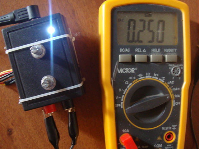
 

Freescale’s sensors breakout boards

A few more PCBs, this time for Freescale’s sensors.

MMA8541Q

The MMA8451Q is a  low-power, three-axis accelerometer with 14 bits of resolution. It communicates over I2C,  has built in tilt/orientation detection and also tap detection.

To make the PCB I downloaded the Eagle files from Sparkfun breakout board and modified it to make it single sided. I had to add a couple of 0 ohm resistors as jumpers.

Freescale sensors

To test it I used Adafruit Library for Arduino

mma8451

FXOS8700CQ

The FXOS8700CQ combines a 14-bit accelerometer and a 16-bit magnetometer. It also has some programmable acceleration event functions, like tap and orientation detection, and includes programmable magnetic event functions: Threshold detection, Vector-magnitude change detection, etc.

Freescale sensors

It  can communicate using i2c or SPI. I used this library to test it.

fx0s8700cq

MPL3115A2

The MPL3115A2 is a pressure sensor that provides altitude data to within 30cm. It has a I2C interface and the outputs are digitized by a high resolution 24-bit ADC. The MPL3115A2  can measure:

  • Pressure: 20-bit measurement (Pascals)
  • Altitude: 20-bit measurement (meters)
  • Temperature: 12-bit measurement (degrees Celsius)

Freescale sensors

I also used Sparkfun’s Eagle files to make the board and I tested using Adafruit Library.

mpl3115a2

According to Google Maps the height where I live is 64.13 m. I was testing the device on a first floor, I would say it’s pretty accurate.

Logic Level Converter

All this sensors are 3V devices. I tried first to connect them to a MSP430 Launchpad using Energia but I couldn’t make them work.

The I2C protocol defines a so-called repeated start condition. After having sent the address byte (address and read/write bit) the master may send any number of bytes followed by a stop condition. Instead of sending the stop condition it is also allowed to send another start condition again followed by an address (and of course including a read/write bit) and more data1.

Freescales’s sensors use this Repeated Start command and as I found out, Energia doesn’t support it. As I don’t have any 3.3V Arduino I needed a logic level converter.

I downloaded Sparkfun files for their  Bi-Directional Logic Level Converter and modified it to make it single sided. I used some 2N7002 transistors I had around.

Freescale sensors

EDIT 19/01:

As requested, here is the file for the MPL3115A2 breakout board. It is based on Sparkfun board but I changed the connector pinout in order to make it easier to design a single sided PCB.

Reference

1. Repeated Start Condition

INA219 Current Sensor DIY Breakout board

Another small board, this time for a INA219. The INA219 is a high-side current shunt and power monitor with an I2C interface.

INA219

For testing I used Rei VILO library with a MSP430G2553 and Energia, and I measured the power consumption for this simple circuit:

2 001-001

Nothing fancy, just a led and a resitor. The INA219 should measure around 9.6 mA and got this:

led_5v_330R

The current measurement is slightly off. I need to play a litlle more with the calibration routines.


SHT21S DIY Breakout board

I made a little board for a SHT21 humidity and temperature sensor from Sensirion.  There are several versions with I2C interface, PWM output and SMD/analog interface.

I’ve got the one with Sigma Delta Modulation (SMD) output,  is a bit-stream of pulses; the more high pulses the higher the value in the full measurement range. A low-pass filter convert the pulse stream to an analog voltage signal.

It has a control pin (SCL) to select between humidity or temperature output. SCL high yields humidity output, SCL low yields temperature output.

SHT21S

I made a simple sketch in Energia to test it out using an MSP430G2553. P1.6 selects between humidity or temperature and P1.0 is used as the ADC input.

SHT21S

…and logged both temperature an humidity.

Sin título

That’s it, a simple and nice sensor…

DIY ez-FET lite…ghetto style

I have a few MSP430G2955 around but non of my Launchpads are capable of programming this MCU. Texas Instruments released a while back all the informtation needed to build the new ez-FET lite. The eZ-FET lite is a low cost USB-based on-board emulation solution for MSP430 microcontrollers. This debuger supports all MSP430 devices compatible with SBW programming and I could use it to program the MSP430G2955.

The hardware is based on an MSP430F5528 and I used a QFN version with an adapter board:

DSC00857

DSC00863

it ain’t pretty…

In order to program the MSP430F5528, I tried first using the FET-Pro430 from Elpotronic. I was able to flash the BSL firmware:

ez2-001

despite an error dialog about code size:

ez1-001

…then, I programmed the ez-FET firmware:

ez3-001

After reseting the programmer all the drivers were installed:

ez4-001

But every time I tried to program a device with CCS I would get this error message:

ez5_error-001

ok, fail…let’s start over.

According to this post the error might be caused by the the custom BSL portion of the ezFET firmware being not properly flashed.  I did read this other post in 43oh about flashing the firmware with MSP430Flasher, I just wanted to see if the Elpotronic software would work.

I tried  to re-program the MSP430F5528 using MSP430Flasher but I get this “BSL memory segments are protected” error.

Sin0-001

According to this post I have to add options to unlock  BSL memory as well as the INFO A memory. I added for that -b and -u:

Sin1-001

Success!! At least the BSL.  Then I attemped a firmware update with MSP430Flasher:

Sin2-001

More success!!! I should have tried this in first place…

Anyway, I tested the programmer with the old and beloved “blink” and It’s working. I still need to test the UART interface but this should work as well.

output_sBDOeU

Avalanche pulse generator- part 2

I build a more permanent version of the pulse generator with some changes. The comparator wasn’t working very well with the 1V reference I was using. I made some measurements with different voltage references and got this:

Vref Vfeedback Vout(measured) (R2/R1+1) Vout(calculated) Error[%]
0,282 1,1 76,8 69,03 19,47 -294,5
0,759 1,087 76,6 69,03 52,39 -46,2
0,953 1,092 77 69,03 65,78 -17,0
1,218 1,258 88,7 69,03 84,08 -5,5
1,243 1,283 90,3 69,03 85,80 -5,2
1,499 1,505 106,3 69,03 103,47 -2,7

The feedback loop was working and the converter regulating but the output value didn’t correspond to the one set it with the feedbacks resistors. The difference between the reference voltage (Vref) and feedback voltage (Vfeedback) is lower with a reference above 1,2V (another source of error is the lack of precision resistors in the feedback divider). and increasing the reference value gives a lower error (difference between the measured and the calculated Vout).  At the end I just put a potentiometer to regulate the reference and tweaked until the converter output was near 90[V].

I started with the oscillator

Multivibrator

Then added the step-up

step up added

And test it

testing the step up

Added the voltage doubler

voltage doubler added

… and test it again…

voltage doubler test

I made a mistake while connecting the oscillator to the step-up. I soldered a cable to the wrong output and was using the inverted signal with a short ON time and a longer OFF time. After changing the output the voltage increased a bit, but  not that much (something like 115[V]). Then soldered in the reference and the comparator.

comparator

Then I connected all together, put the resistor divider to get the voltage feedback and set it to 80V

dc-dc converter set it to 80[V]

Finally soldered the transistor, 50 ohm termination and BNC

Avalanche pulse generator

The board with the different blocks labeled,

Avalanche pulse generator

and finally made some measurements.

Avalanche pulse generator

The formula to calculate the bandwidth based on the rise time is BW=0.35 / rise time [ns], I measured somewhere near 2.5 [ns], but that is a bandwidth of 140 MHz. That’s a lot higher from what I was expecting (I have a DS1052E without the bandwidth hack, so it’s 50Mhz). I’m probably doing something wrong but I don’t know what…

Avalanche pulse generator- part 1

I wanted to make a fast pulse generator like the one designed by the great Jim Williams1. Unfortunately, the required chip for the high voltage power supply (LT1073) is not available where I live. I found several similar circuits using different approaches to generate the required voltage. I particularly liked the one in Dangerous Prototypes2, in which an astable multivibrator made with transistors is used to drive a step-up and It got me thinking ¿could be possible to “make” the entire LT1073 with transistors?

I looked for the datasheet3 and found a block diagram of the device.

bloque

Figure 1. LT1073 internal block diagram.

Comparator A1 compares the feedback pin voltage (Fb) with the internal voltage reference. When the feedback drops below 212mV the comparator A1 switch on the oscillator. The driver amplifier boosts the signal level to drive the output NPN power switch Q1. The switch cycling action raises the output voltage and the feedback pin voltage. When the feedback voltage is high enough the comparator turn off the oscillator.

Oscillator

I made the oscillator with an astable multivibrator (like the one in DP). I opted for the version with waveform correction4.

osc

Figure 2. Astable multivibrator with diodes for edge correction and a transistor to control it.

I added a transistor to control the oscillator. When the feedback voltage is lower than the reference the comparator goes low and the oscillator is activated in order to rise the output voltage. According to the datasheet the oscillator is set internally for 38µs ON time and 15µs OFF time. I calculated the resistors needed using a 1nF capacitor but later on I tweaked the values in the breadboard until I got close enough to the required ON and OFF time.

NewFile43

Figure 3. Oscillator output.

Voltage reference

For the reference I made a variable zener with a pair of transistors5.

zener

Figure 4. Variable zener.

I set it to 1V and made some measurements to see how stable the reference was:

Figure 5. Reference voltage (yellow) with power supply variations (blue)

The measurements were done with the converter working making the reference voltage quite noisy. Without a 1uf capacitor between Vref and ground (not shown in the schematic) it looked even worse:

NewFile14

Figure 6. Voltage reference without the 1uf capacitor.

These are the measured values in a much compact graph:

Ref output_vs_vcc

Figure 7. Voltage reference output with variations in voltage supply

Comparator

I build the simplest comparator I could find:

comp

Figure 8. Comparator schematic.

For testing I connected the (-) input to a potentiometer and the other input to the oscillator output:

comp_test

Figure 9. Comparator test setup.

Moving the potentiometer up and down changes the comparator output width:

image

Figure 10. The comparator output is the yellow trace, the potentiometer value is at the top left corner and the blue trace is the oscillator output.

It is not the best comparator you could find but it is good enough for this application. I’m not using hysteresis like the comparator inside the Lt1073 does.

Switching transistor

Tried first with a single BC548 but couldn’t get more than 30V, adding a 2N2222 in a Darlington configuration I could reach a little more than 50V:

Sw

Figure 11. Output Darlington switch.

I also added a diode-capacitor voltage step-up network (as in the original circuit with the LT1073) and this is what the final circuit looks like:

sch

Figure 12. Complete schematic.

and the block diagram of my version:

bloque2

Figure 13.

Then did some test to see if the whole thing was regulating properly and how the output changed with voltage supply variations.

HVoutput_vs_VCC

Figure 14. Output (yellow) vs power supply (blue).

Again the values from the previous oscilloscope captures in a single graph:

HV output_vs_vcc

Figure 15. High voltage output from the converter with variations in the power supply. The converter is configured to output a little bit more than 82V.

I also made some captures of the output from the oscillator as the supply voltage decrease:

osc(blue)_HV output(yellow)_variable VCC

Figure 16.

It can be seen how the pulse trains increase with the reduction of voltage supply. With voltages lower than 1,7 V the converter can’t regulate properly.

I was able to source locally the 2N2369 used in the original application. I connected it in the protoboard to see if the converter could get it to avalanche. The blue trace (Figure 16) shows the voltage in the capacitor, it charges until the voltage is high enough to avalanche the transistor rapidly discharging and generating a fast rising pulse shown in the yellow trace.

NewFile39

Figure 17.

All this testing was done on the protoboard so is no surprise that the pulse looks like crap:

NewFile38

Figure 18. Collector capacitor discharge (blue) and pulse from the avalanche transistor (yellow). It can be seen that the breakdown voltage is around 67[V]

I used a 22pF capacitor but even without using one the parasitic capacitance in the protoboard where high enough to make it work anyway. Now I need to build a proper board.

Reference

1. Application Note 72, APPENDIX B, Measuring Probe-Oscilloscope Response
2. Avalanche pulse generator, and some scope porn
3. LT1073 Micropower DC/DC Converter Adjustable and Fixed 5V, 12V
4. Transistors Tutorial, Part 7: “Oscillators”
5. Simple Transistor Circuits For Experimenting, Fun and Education. Variable Zener Diode

Constant Current Electronic Load

I’m building a power supply and an electronic load might be useful for testing it, so I made one.

Electronic Load/ Carga electrónica

The design is based on some of the various diy electronics loads out there (like the one from Dave Jones). The mosfet is a P45N03LT , most likely I took it from some of the PC power supply I’ve “recycled”.  I’m using two 25k potentiometers, one for coarse adjustment and the other for fine adjustment (10 turn pots are kind of expensive…). The control voltage varies between 0 and 5 volts and is divided by two with a couple of 10k resistors. The op-amp is an OPA2336, It has rail to rail output so the load can sink roughly up to 2,5. The op amp is powered with a 7805.

Electronic Load/ Carga electrónica

The sense resistor is made with a series of 10 0.1 ohm, 1[w], 1% resistors. I made two “resistors” soldering 5 of them and then I put these two back to back and used kapton tape to keep them electrically isolated.

Electronic Load/ Carga electrónica

Finally a heat sink (scavenged form a PC supply as well) for the mosfet and some female banana plugs. The heat sink is too small and it gets really hot, I will have to find a bigger one or put some kind of cooler fan.

Electronic Load/ Carga electrónica

A few components for a very handy piece of equipment.

Electronic Load/ Carga electrónica

Making an FM radio-Part 2; the incremental encoder

Despite being a digital radio capable of doing a lot of stuff I wanted a simple design with a knob for volume and another one to change station. The volume is just a potentiometer and for the stations I wanted to use an encoder, unfortunately I didn’t have one. What I did have is a hard drive motor and as it turns out you can use them as rotary encoders. I found two ways to do this; one is to use the signals from the hall sensors and the other one is to use the back fem generated by the winding. The motor has all the electronics sealed making it difficult to figure out how to use the sensors so I used the second method. I found two projects that use brushless motors as encoders taking advantage of the back EMF. In one op-amps are used as amplifiers and the outputs are sampled with a microcontroller’s ADC, in the other the op-amps are used as comparators thus generating a couple of square waves. With the second approach I could use interruptions instead of sampling both ADC channels all the time so I went for the comparator setup.
For the first tests I used only a couple of led at the op-amp outputs to see if the circuit was doing something. Then I watched the outputs with a logic analyzer and let me tell you, it wasn’t pretty. Anyway, I searched for ways to read encoder signals with a microcontroller and I found this. I copied that code and add it a few lines to have a couple of pins generating pulses depending on the direction of rotation.

Unfortunately that code was made to be used with a real encoder with a much cleaner signal. In the picture I’m moving the motor in one direction but both outputs (channel 2 and 3) are generating pulses.

If you use an optical encoder all you have to do is detect a flank (either low->high or high->low) in one signal and check the value of the other one. With my “encoder” I have to detect both flanks and check the values of the other signal in those situations to see if an acceptable sequence has occurred.  And after a few changes I got this;

The first picture shows the signals generated when I move the motor fast first in one direction and then in the other. In the second picture I’m moving the motor slower (as if I’m looking for a station) in only one direction.  The signal is worst when I turn it slower but the microcontroller managed to detect a few pulses which I’ll be using to control the radio. Finally the code;

#include <msp430g2452>;
#include "stdint";
int aux=0;
int edge=1; //0=high-&gt;low, 1=low-&gt;high
int dir=0;
int accept=0;
void main( void )
 {
 // Stop watchdog timer to prevent time out reset
 WDTCTL = WDTPW + WDTHOLD;
BCSCTL1 = CALBC1_16MHZ; // Set range
DCOCTL = CALDCO_16MHZ; // SMCLK = DCO = 16MHz
P1REN |= BIT1 + BIT2;  // select pullup resistors for pin 1.1 and 1.2
P1DIR |= BIT5 + BIT4;  // outputs for testing
P1OUT |= BIT1 + BIT2;  // need to set P1.1 and P1.2 to high so PULLUP resistor will be selected
P1IES &= ~ BIT2;  // select low to high transition for interrupts on all port pins (this actually the default)
P1IE  |= BIT2;  // enable interrupt for P1.2 to reader status of encoder every time Encoder sigal A goes high
P1IFG = 0x00;  // clear interrupt register
__bis_SR_register(LPM0_bits + GIE);
for (;;) {
}
}
#pragma vector = PORT1_VECTOR
 __interrupt void InterruptVectorPort1()
 {
 if( P1IFG &amp; BIT2 ) {
    switch(edge){
     case 1://always start with the 0-&gt;1 edge
      aux=( P1IN &amp; BIT1 );//save the other channel input
      P1IES =BIT2; //Edge sensitivity
      edge=0;//the next interruption will be in 1-&gt;0
      accept=0;//reset value
     break;
     case 0:
      if((P1IN & BIT1)==aux){accept=0;}//Not a good pulse sequence;
      else{accept=1;//Good pulse sequence
      P1IES &= ~BIT2 ; // Toggle Edge sensitivity
      edge=1;
      if(P1IN & BIT1){dir=2;}//save direction of movement
      else{dir=1;}
     break;
 } if(accept){//if a good sequence is detected...
    switch(dir){//output a short pulse in the correct direction
     case 2:
      P1OUT |= BIT4; // output P1.4
      __delay_cycles(1500);
      P1OUT &= ~BIT4;
     break;
    case 1:
      P1OUT |= BIT5; // output P1.5
     __delay_cycles(1500);
     P1OUT &= ~BIT5;
    break;
 }
 }
 P1IFG&= ~ BIT2;
 }
}