This is kind of a Hello World! post. It is my first attempt with a blog and there will be a led blinking at the end.
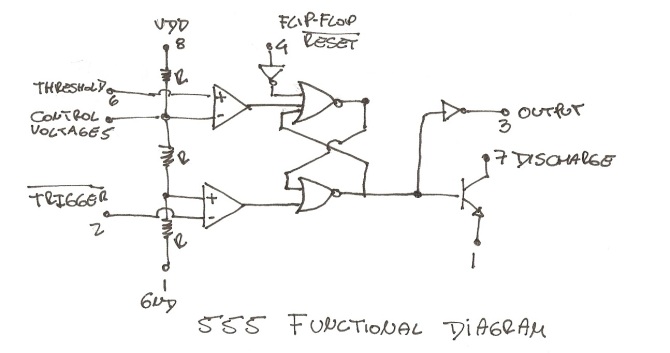
For some reason I am always amused by those circuits that only use transistors like this clock or this 4 bit computer. For a while I’ve been wanting to build a 555 timer using transistors but I didn’t want to make those over complicated circuits that appears in datasheets. I wanted to make a simpler circuit in which I could be able to test the different blocks separately. What blocks? These blocks;
You might have seen this kind of diagram in datasheets and other places, the figure above shows clearly the different parts that makes a 555 timer. The next step was to find the simplest circuit for each part.
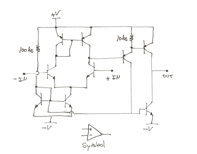
For the op-amp I ended up using this circuit;
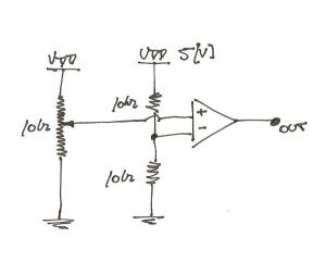
All the PNP transistors are BC558 and the NPN are BC548. Testing the comparator it’s easy. I used this simple circuit that appears below and you only need a multimeter and a power supply to do so. The output is around 0,4 volts when you have less than Vcc/2 (2,5 [V]) on the non-inverting input. If you move the potentiometer slightly above 2,5 volts the output voltage sharply transition up to Vdd.
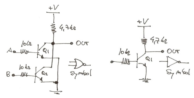
Then it was time for the logic gates. I found a couple of circuits here;
Once again testing these circuits it’s trivial, just hook up a multimeter to the output (you could use a led) and connect the inputs to “0” (GND) and “1” (VCC) and check the truth tables of the differents gates.
This is how the final circuit looks after connecting all the circuits together
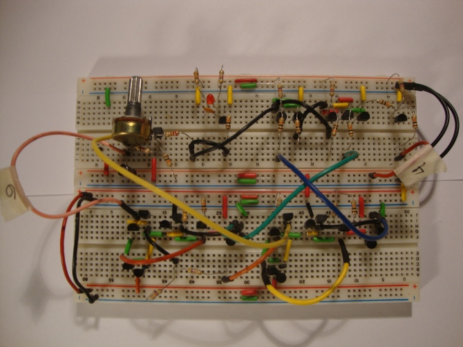 There are more pictures here. And finally a short video showing both basic configurations: Astable and Monostable.

Very Nice! Thank you! Building a 555 out of discrete components is one of the things i want to do to learn more about electronics.
hi, please check limitations “from 2-25 pF per contact point” http://en.wikipedia.org/wiki/Breadboard good hob
Very cool!! You make it look so easy. Could you provide some sources or an explanation of how the op-amp/comparator works?
Thanks! I can’t remember the exact source for that schematic. I remember having read this article: https://www.passdiy.com/pdf/diyopamp.pdf, it explain the different parts: the differential pair, and output stage and current sources.
Evil Mad Scientist Laboratories made a kit a while back for a 741 om amp, all with transistors. It is a much more complex design but I think it migth be helpful: https://cdn.evilmadscientist.com/KitInstrux/741/741_principles_RevA104.pdf
They also have a 555 kit: https://cdn.evilmadscientist.com/KitInstrux/555/555_principles_revB3.pdf, but they used a different design for the comparators.